Technical Information
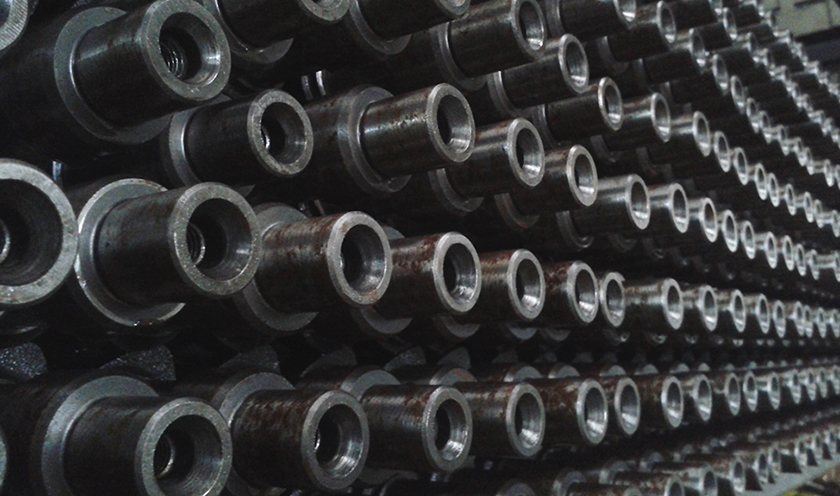
Camshafts
Technical Aspect
Mechanic part receiving movement from the crankshaft through a set of components and transmits it to the valves, where it is transformed into alternating rectilinear motion.
In those engines running in the four-stroke cycle, the camshaft is constituted by a carbon steel shaft, where some cams are mechanized, in a number equal to the motor valves. each engine´s valve opens and shuts for each complete cycle, the leading cam turns one turn in each cycle, wherefore in the for-stroke engines the camshaft will torn once for each two turns of the crankshaft. the angular distribution of each cam composing the drive shaft synchronizes the opening and closing starting times of the admission and exhaust cycles of the engine assembly. with an appropiate profile on both cams of a cylinder, it is achieved to lift the valves up to an convenient height and keep them open during an ideal period of time in order to obtain the optimal performance of the engine.
The maximun opening achieved for the valve is called throw.
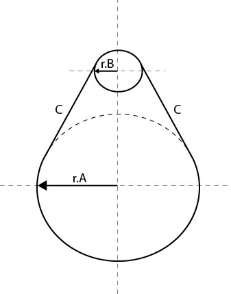
The profile of a valve generally comprises:
In those engines running in the four-stroke cycle, the camshaft is constituted by a carbon steel shaft, where some cams are mechanized, in a number equal to the motor valves. each engine´s valve opens and shuts for each complete cycle, the leading cam turns one turn in each cycle, wherefore in the for-stroke engines the camshaft will torn once for each two turns of the crankshaft. the angular distribution of each cam composing the drive shaft synchronizes the opening and closing starting times of the admission and exhaust cycles of the engine assembly. with an appropiate profile on both cams of a cylinder, it is achieved to lift the valves up to an convenient height and keep them open during an ideal period of time in order to obtain the optimal performance of the engine.
The maximun opening achieved for the valve is called throw.
The profile of a valve generally comprises:
- Circunference section of the radius a, defined as base circle, which correspond to the closing period of the valve.
- Circunference section of the radius b, defined as crest, which corresponds to the maximum opening stage.
- Two rectilinear or curvillinear c sections tangent to the former ones, called flanks, which correspond to the valve´s opening and closing starts.
Basic checking camshaft
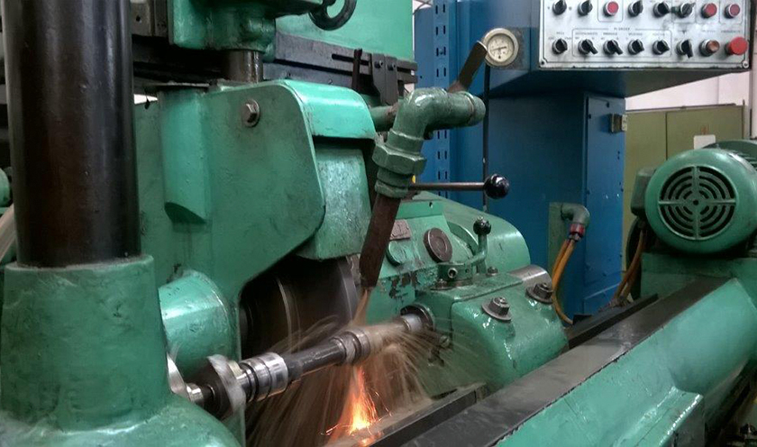
Bearing surfaces and cams profile mus not present signs of wear, scratches, grips, etc admitted roughness up to 0.1 m surface cam 0.2 m surface bearings.
- Gear movement distributor and oil pump, may not present excessive wear
- Fuel pump control eccentric may not present excessive wear displacing: is controlled placing the camshaft, resting on its extreme bearings in two v placed on a surface plate, checking with a comparator, which toucher is in contact with the central bearing (of a camshaft), once conformed said method of control, start turning the camshaft, not exceeding the comparator´s reading difference over 0.03 m.m.
- Throw: start placing the camshaft in the same way as in the method before the control (off-center), touching with the comparator the cams and turning it, the maximun and minimun reading difference which may not exceed 0.06 m.m. for all the admission or exhaust valves, whereby both groups may be differentiated between themselves.
- Bearing: will be checked with micrometer, and may not exceed 0.02 m.m. diminishing the minimun allowance specified by the manufacturer.
Basic considerations of the asembly:
- Clean all the components
- Check the contact surface of the drifts with cams.
- The maximum axial clearence must be 0.15 m.m. between the housing and bearings.
- Verify the alignment of the housing.
- Replace at the same time the camfollowers.
- Drain and flush the engine before starting work as hidraulic lifters.
- Lubricate bearings, cam and camfollowers.
- Appropiate spring-loaded according with technical specifications.
Start-up
- Check oil level.
- Check oil pressure according with technical specifications.
- Avoid the extended first start-up with battery.
- Run the engine up to 1500-2000 rpm during half an hour, forcing the lubrication of the tappets and facilitates the settlement of it.

Oil pump
Technical Aspect
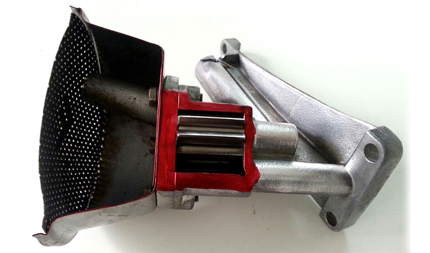
The oil pump is an engine part assemply complying with the function of circulating oil at a certain pressure, lubricating it.
The requested oil pressure automatically adjusts itself according to the engine´s clearence through the circuit when the pressure increases in excess due to the increase of the oil regime through a ball or piston wich remains closed at low pressure against the casing´s seat due to the pressure exerted by a spring.
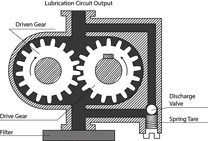
On the scheme you can see that both turns of the gear are in the sense indicated by the arrows, drifting the oil through the inmersion in the pan, which flows between the spaces of the pinion´s teeth and the walls of the pump´s body, getting to the corresponding chamber of the oil´s driven to lubricate the engine´s components.
Checking the lubrication system
Low pressure
- Check the oil viscosity (wasted or diluted).
- Check pump´s strainer or oil filter partially obstructed, will be free of impurity.
- Replace the oil pump.
- oil not appropriate for the engine type or season of the year.
- jammed reliev valve.
- partially obstructed ducting of the engine circuit. in case to be dirty replace it with appropriate oil and let work the engine for half an hour.
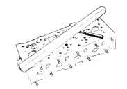
Cylinder Heads:
The head is strongly joined at the block and to fix them completely, the gasket must be put between them. this last one, is made of flexible materials that may bear the warmest engine temperatures. the gasket close the combustion engine cylinders to avoid loosing compression. it also contains the camshafts, the sparkplug (in gasoline engines), intake and exhaust valves and water ducts to refresh it. it is manufactured with ironworks melted with other materials, adding resistence, stiffness and thermal conductivity. sometimes melted aluminium is used in manufacturation. this material combines lightness and a high thermal conductivity, which is a very important characteristic. it does not allow that heat combustion, goes outside and avoiding warm spots that may cause explosion.
The compression ratios increases with these heads and improves engine performance.
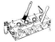
How to remove head in engine: as the correspondent join is fixed to the block, to remove the head please don`t use any screwdriver or any other tool that matchs between them. to remove it, knock softly a corner of the head with a plastic hammer, trying to make it turn round on itself, just where it is fixed on the block. head can also be removed turning round the crankshaft, so the pressure generated inside the cylinders, removes it. in this case, don`t remove completely fix screws; just turn them round lightly.
How to clean the head: before making checkups, clean the components carefully, in orde to detect there is no erosion, inappropriate scratch, damages, etc. when checkup finishes, any component must be completelu soaked in oil to avoid possible damages for stiffness during the first period.
Once the cylinder block is clean, please check up it, being sure of having taken every particle stick to the union surfaces, containing gaskets, such as head area,oil sump among others.